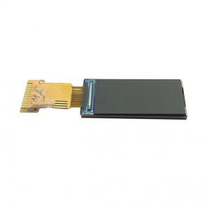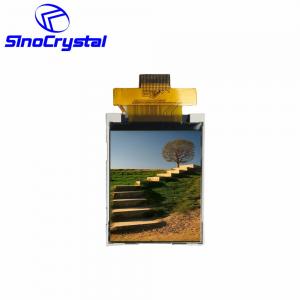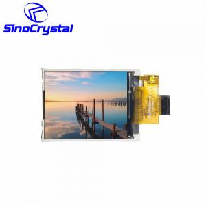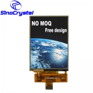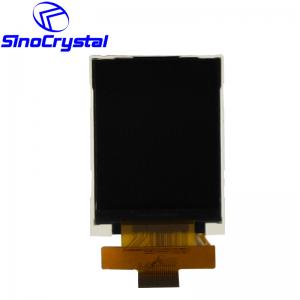

SCT018001-V02是彩色TFT 128x160液晶显示模块,对角线尺寸为1.77英寸。该模块内置ST7735S-G4芯片,支持8位MCU接口。最佳可视角度是12点钟方向。
型号:
SCT018001-V02Size (inch)尺寸(英寸):
1.8寸分辨率:
128*160外形尺寸(mm):
34.00*45.83*2.60可视尺寸(mm):
31.832*41.420视域尺寸(mm):
28.032*35.040视角:
12接口:
8bit MCUIC型号:
ST7735S亮度(cd/m m2):
350触摸:
No温度 (℃):
-20°C~70°CBasic Information
Resolution: 128x160
Outline Dimension: 34.00*45.83*2.75
Active Area: 28.032*35.040
View area: 31.832*41.420
Interface: 8bit MCU
Driver IC: ST7735S
View Direction: 12 o'clock
PIN: 20
Backlight: White LED
Touch Screen: No touch screen with standard module, But can be added if customer needed.
General Specification
| Item | Nominal Dimension | Unit |
| Dot Matrix | 128 x RGB x 160 | Dots |
| Module Size ( W×H×T ) | 34.0 x 45.83 x 2.75(max) | mm. |
| Active Area ( W×H ) | 28.032 x 35.040 | mm. |
| Pixel arrangement | RGB Stripe | mm. |
| Dot Pitch ( W×H ) | 0.219 x 0.219 | mm. |
| Color depth | 262K(MAX) | colors |
| Interface | 8 bit MCU | - |
| Driving IC Package | COG | - |
| Operating temperature | -20 ~70 | ºC |
| Storage temperature | -30~80 | ºC |
| LCD Type | a-Si TFT | - |
| LCD Mode | TN/Normal White | - |
| Backlight Type | LED x 2 | PCS |
Interface Definition
Pin No
Pin Symbol
Level
Description
1
LED-
-
LED light, cathode.
2
LED+
-
LED light, anode
3
GND
0V
Ground
4
VDD
2.3-3.6V
Power supply
5
NC
-
Dummy
6
NC
-
Dummy
7
/CS
H/L
Chip Select signal
8
/RESET
H/L
Chip reset signal
9
RS
H/L
Register select signal. 0:index register; 1: data register
10
/WR
H/L
Write signal
11
/RD
H/L
Read signal
12
DB7
H/L
data bus 7
13
DB6
H/L
data bus 6
14
DB5
H/L
data bus 5
15
DB4
H/L
data bus 4
16
DB3
H/L
data bus 3
17
DB2
H/L
data bus 2
18
DB1
H/L
data bus 1
19
DB0
H/L
data bus 0
20
GND
0V
Ground